
Designing SRT failover for real network faults
SRT failover earns its place during the faults that leave a connection looking healthy while the programme freezes. Pulling a cable is a useful first test. A credible acceptance plan also covers congestion, silent packet loss, broken return traffic and a primary path that repeatedly disappears and returns.
Start by defining the viewer impact you can accept. Record the maximum picture interruption, audio gap and recovery time, then test the complete chain against those limits. A receiver changing its selected input proves only one part of recovery.
Choose the SRT failover mechanism deliberately
Secure Reliable Transport (SRT) uses automatic repeat request (ARQ) to recover missing packets through retransmission. Live-mode buffering gives recovery time; packets that miss their delivery deadline can be dropped. The SRT library’s socket-option documentation defines these controls. Retransmission still depends on a working path between sender and receiver.
Switching between independent feeds
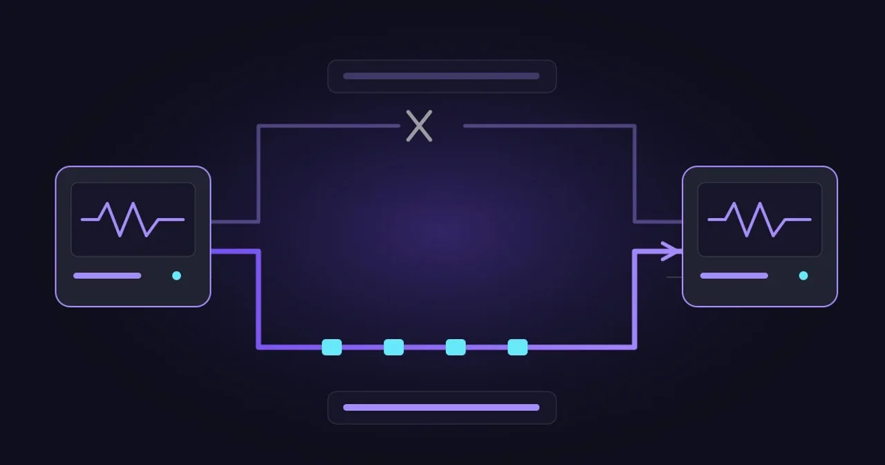
A receiver can accept two SRT feeds, monitor them and select one for output. Each feed can have its own encoder, connection and timing. The receiver must decide when to switch and how to handle the transition between those media streams.
AWS MediaConnect’s router-input documentation provides a concrete example: its SRT inputs support source failover, while its packet-merge option applies to other listed protocols. The documented trigger is 500 milliseconds without source data. That is a product-specific detection interval, not an SRT protocol guarantee or a promise about the visible interruption.
Protecting packets with connection groups
SRT connection groups coordinate several connections carrying one submitted data stream. Broadcast mode sends duplicate data over member paths and discards duplicates at reception. Main/backup mode normally sends payload on one path, with other connections available for takeover.
The SRT connection-bonding quick start, maintained in Haivision’s open-source repository, documents specific build and application requirements. Confirm group support at both ends, the installed library configuration and who reconnects failed members. A device labelled SRT-compatible may expose only ordinary connections.
Broadcast-mode redundancy consumes bandwidth on each path. It also leaves common sender and receiver failures to address separately. Two independently encoded versions of the same programme cannot simply be treated as duplicate packets in a group.
A. Switch between independent feeds
The receiver selects a complete feed. Independently encoded feeds can have different timing and packet sequences; test the media transition.
B. Duplicate packets with an SRT broadcast group
The same submitted data travels on both paths. Requires compatible group-aware applications at both ends. Each path carries the payload; common endpoint failures remain.
Broadcast-group mode shown. In main/backup mode, payload normally travels on one member path. These are architectural patterns, not a claim of Evrideo group support.
Draw the shared failure points
Trace both routes through the encoder host, network interface, access switch, firewall, internet circuit and receiving infrastructure. Ask which power supply, last-mile duct, upstream network or cloud component can interrupt both.
Different destination addresses establish very little by themselves. Two interfaces can still use the same router. Two carriers can share a physical entrance. Record the independence you have verified and the shared risks that remain.
Decide separately whether you need protection against network loss, encoder failure, receiver failure or loss of a whole site. A duplicated network path from one encoder protects a different failure boundary from two complete contribution chains.
Two network routes
Either circuit may survive a network fault. Losing the shared encoder, router or receiver can interrupt both routes. Trace power, physical access and upstream infrastructure too.
Budget time through to decoded media
Measure three intervals: detecting the fault, obtaining usable replacement media and restoring downstream playback. Existing buffers can hide some disruption, while waiting for a decodable access point or rebuilding programme state can extend it. Measure the result instead of treating these intervals as a universal additive formula.
Record round-trip time (RTT), variation in delay, retransmissions and unrecovered drops under realistic load. Include the slower route. A backup needs capacity for the full programme and recovery traffic when it becomes active.
Consider a hypothetical 12 Mb/s contribution feed with primary RTT of 40 ms and backup RTT of 150 ms. Those numbers alone cannot determine a safe latency setting. Inject the expected loss bursts and congestion, verify when replacement packets arrive, and observe whether the receiver still meets its delivery deadlines. Repeat with competing traffic and both routes impaired.
Reconnection settings also deserve inspection. GStreamer’s SRT source documentation distinguishes caller reconnection from whether a listener waits after disconnect. Automatic reconnection does not establish a second usable programme path. Test the deployed application, including authentication failures and process restarts.
- t0Inject the fault
Packet loss, a silent blackhole, source freeze or process failure.
- t1Detect and select
Record the alarm and input-selection timestamps separately.
- t2Obtain usable media
Check programme tables, timestamps and a decodable access point.
- t3Verify decoded output
Measure picture and audio recovery, captions and SCTE-35 continuity.
- t4Restore protection
Repair the failed route, test standby readiness and apply the agreed failback policy.
Illustrative milestones, not a scaled timing chart. Steps can overlap and buffers can mask faults. Measure actual visible interruption at the output; do not add these stages to predict it.
Check the programme after switching
For MPEG transport streams, compare programme identity, packet identifiers, programme tables, codec configuration and timing across the feeds. Match the required audio tracks and captions. Check random-access availability and establish how the receiver handles any timestamp discontinuity.
ETSI TR 101 290 provides transport-stream measurement guidance covering programme tables, continuity counters and PCR/PTS timing. Use those measurements alongside decoded picture and sound. An established SRT session can carry a frozen picture, missing audio or damaged programme signalling.
Capture the output before, during and after switching. Inspect audio/video alignment, captions and SCTE-35 markers, including a switch during an ad break. When a packager and streaming player follow the receiver, include them in the rehearsal: the final playback experience is the acceptance point.
Rehearse faults that resemble production
Use an isolated test route or an approved maintenance window. Agree thresholds first, identify a rollback owner and record software versions, settings and synchronized timestamps. The following is an engineering test plan, not a claim about measured customer results:
- Inject random loss, burst loss, jitter and reordering. Compare retransmitted packets with unrecovered loss and visible output faults.
- Silently discard UDP traffic, then impair the reverse direction separately. Detection must work without a clean disconnect message.
- Restrict capacity and increase path-delay differences. Confirm that the surviving route carries the service under load.
- Restart senders and receivers, and test incorrect backup credentials. Check that alarms identify an unusable standby.
- Restore the primary repeatedly. Observe switching behaviour and test a second failure after recovery.
- Freeze the source picture or remove audio while packets continue. Confirm that programme-level monitoring detects the problem.
For each test, record fault injection, alarm, path selection, usable output and restored redundancy. Preserve output evidence as well as network counters. A successful first switch followed by an unrepaired backup leaves the next incident exposed.
Agree the return-to-primary policy
Document whether the system returns automatically, waits for a stability interval or requires an operator. In the AWS example, a configured primary is selected again when data returns. Other implementations differ. Frequent switching during an unstable recovery can interrupt viewers repeatedly, so rehearse the actual policy.
Evrideo Outpost provides configurable primary and backup routes, SRT visibility and transport-stream monitoring. StreamCheck supports pre-flight SRT diagnostics. Use these capabilities to gather evidence, and confirm the specific receiver behaviour required by your design rather than assuming packet-group support or lossless transitions.
Sign off SRT failover with an agreed fault matrix, measured output recovery and a named owner for restoring redundancy. Talk to Evrideo about the contribution routes and acceptance tests for your channel.
Related Articles

OTT Distribution Strategy: How to Reach Every Screen Without Breaking Your Budget
February 20, 2026 · 8 min read
What makes a good FAST distribution deal?
October 9, 2026 · 6 min read
Live sports overruns: coordinating changes with AI agents
October 7, 2026 · 6 min read